| Home |
GENERAL DESCRIPTION
COMPUTERIZED CROWNER RETROFIT SYSTEM
Essentially, any grinder with a pivot trunnion axis is a candidate for the RGB retrofit crowner system. This includes the vast majority of roll grinders originally supplied with mechanical type crowning devices, whether they be of the cam or former bar style of mechanism. The new crown control functions as a "stand-alone" system working in conjunction with the existing grinder control unit. The RGB crowner is essentially controlling the wheel path as a function of carriage (or table) position. In this capacity, it is not unlike the mechanical crowning device, except of course for the many additional features available with the new system.
For cam type crowners, the new servo drive interfaces with a portion of the cam drive gear train to produce cam rotation, but with a different operating principle. In order to fully appreciate the significance of these concepts, a brief review of a typical conventional crowning arrangement is necessary. This example is based on a Farrel tilt infeed style grinder, although the principles are essentially the same for any type of cam crowning system.
A pinion meshing with a rack on the side of the back bed drives through bevel gears to a set of change gears, with the driven change gear on the crown drive shaft. Miter gears, which move with the subbase, engage the crown drive shaft through a splined key arrangement. The output miter gear is on a vertical crown worm shaft which meshes with the worm gear on the cam shaft. Therefore, as the carriage traverses along the bed, the cam rotates.
The "cam" is really not a cam in the true sense, but rather an eccentric which is offset a specific amount from the true center of rotation (actually, there are some older grinders that do use a specially machined cam rather than an eccentric - these are even more restrictive in crown shape options). A cam follower bearing, supported in a vertical slide member, rides the eccentric, and imparts this crowning motion to the back of the wheelhead. The final mechanical advantage is achieved through the tilting wheelhead. This consists of a simple trunnion pivot arrangement, with support points at the two front pivots and the center-mounted follower bearing engaging the cam at the rear. Mechanical superposition of the crown input with the normal tilt infeed ball screw at the front of the wheelhead is achieved with this system.
It is important to
recognize that the crown shapes that can be produced from this kind of bellcrank
eccentric are sinusoidal in nature, since the principles of simple harmonic
motion apply. Over the years, it has been found that a 70 degree portion
of a cosine curve (the cam rotates +/- 70 degrees fro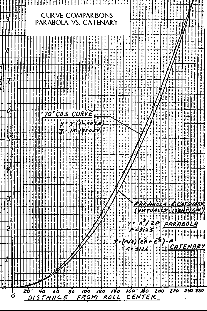 m the TDC position) most
closely approximates the desired theoretical catenary or parabolic crown shapes
required to compensate for roll deflections in the mill (see the sample plot on
the right). It is a simple matter to vary this shap
m the TDC position) most
closely approximates the desired theoretical catenary or parabolic crown shapes
required to compensate for roll deflections in the mill (see the sample plot on
the right). It is a simple matter to vary this shap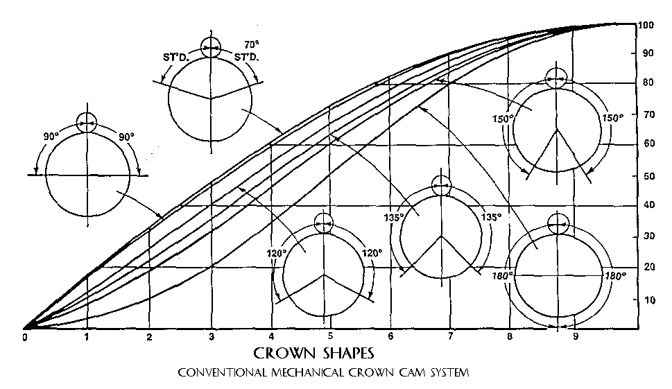 e to other cosine
angles (i.e.: 90 degrees, 120 degrees, etc.) by using different combinations of
change gears (see the crown shape profiles on the left). A chart is
usually provided to select the appropriate change gears for a particular roll
face and angle of cam rotation. But no matter what combinations of gears
are used, the crown will always be a portion of a cosine curve. The amount
of crown is controlled by fixing the total offset of the cam through the vernier
adjustments built into the cam mechanism. The crown charts tabulate these
offsets or eccentricity as a function of the required crown.
e to other cosine
angles (i.e.: 90 degrees, 120 degrees, etc.) by using different combinations of
change gears (see the crown shape profiles on the left). A chart is
usually provided to select the appropriate change gears for a particular roll
face and angle of cam rotation. But no matter what combinations of gears
are used, the crown will always be a portion of a cosine curve. The amount
of crown is controlled by fixing the total offset of the cam through the vernier
adjustments built into the cam mechanism. The crown charts tabulate these
offsets or eccentricity as a function of the required crown.
This mechanical system as described has served the industry well over the years. Its main attribute is simplicity of operation which has made it a reliable and accurate method of producing crown shapes. But with the advancements in rolling technology, which are challenging the roll grinders to provide roll contours not definable by sinusoidal or parabolic shapes (as with compound crowns and CVC curves), it is time to consider a more flexible crowning system to meet these requirements. The RGB Engineering computerized crowner system uniquely addresses this issue, by retaining the basic elements of the proven cam type crowner mechanism for actuating the crown tilt system (SCA), and combining it with a state of the art computer based digital Flexible Function Generator (FFG) and customized software (FFP), for producing any desired roll shape.
On the older style grinders without crown cams (i.e.: Churchill former bar type), or for certain grinders originally manufactured without the cam mechanism, but with a tilt axis, a ball screw type actuator is used to pivot the wheelhead. This is referred to as a Servo Linear Actuator (SLA), and is available as an optional approach on any style grinder.
FFG: Flexible Function Generator
FFP: Flexible Function Programmer
SCA: Servo Cam Actuator or, SLA: Servo Linear Actuator
Concepts of FFG/FFP/SCA
The SCA system uses the existing eccentric cam with a preset offset to actuate the wheelhead tilt infeed system in the conventional manner. The existing drive train is essentially decoupled at the change gear interface. On what was the "driven" change gear side, a DC servo motor operates through a harmonic drive reducer into the conventional gear train to produce cam rotation. Backlash in the gear train between the harmonic drive and the cam should be minimized to assure maximum performance. However, with the SCA concept, the cam always operates on one side of TDC, so gravity forces constantly act to produce a natural preload on the gears. This is an inherent advantage of the SCA system compared to the conventional cam approach.
The "drive" change gear shaft is used to provide carriage position input, by connecting a multi-turn absolute encoder though a timing belt connection to produce a linear output as a function of carriage (or table) position. This is a true "absolute" encoder that does not lose its memory with loss of power. Therefore, no "homing" cycles are required to establish a coordinate reference position when powering up. The encoder feeds a digital display as well as producing the signals for the "x" axis of the crown profile.
The cam is offset a specific amount (to be determined for each application for optimized performance); there are no further adjustments required to the cam. With this fixed eccentricity, the wheel infeed can be controlled very accurately with the DC servo motor.
The command signals are produced by the FFG, which is located in a free standing enclosure on the floor. Click on "Hardware" below, then "FFG Station" for more details. The FFG receives digital inputs from the carriage position encoder and produces digital profiles using the FFG/FFP software (click on "FFP Profiles" for a description of the software profile generation routines). The outputs go through a D/A, then into summing circuits to command the servo motor for "y" axis positioning.
Since the crown actuator is non-linear, a LVDT (linear voltage displacement transducer) is mounted on the back of the cam follower assembly in such a manner that it sees only the crown component of motion. This then forms the linear feedback to complete the positioning servo loop.
With this setup, the cam always operates on one side of top dead center, with one direction of the servo motor feeding the wheel "in", and the opposite direction moving the wheel "out". This is in contrast to the conventional mechanical cambering system, where the cam rotates equal angles either side of top dead center, and the direction of the cam rotation does not directly equate to wheel infeed or outfeed. It is important to understand this basic difference in the operation of the two systems. Click on "SCA Principles" below for additional information on this subject.
There are two primary advantages of the RGB Engineering SCA concept, compared to a conventional ball screw or wedge type actuator:
First, the cam is an extremely accurate and efficient method of applying precision infeed to the wheel. Since the cam and its associated drive mechanism already exists, it is only logical to take advantage of it, for accuracy as well as cost reduction reasons (in short, why reinvent the "cam"?). This mechanism is a proven system, with which maintenance mechanics are familiar with, and for which spare parts probably already exist.
Second, since the mechanical cam and drive assembly are not being disturbed, the unit remains essentially intact as a standby back up system ready to be employed should a catastrophic failure occur to the computer or other critical hardware. This feature usually appeals to seasoned mechanical maintenance people who have experienced problems when sophisticated electronics have replaced long time reliable mechanical devices.