| Home |
FFP PROFILE GENERATION
COMPUTERIZED CROWNER RETROFIT SYSTEM
The RGB
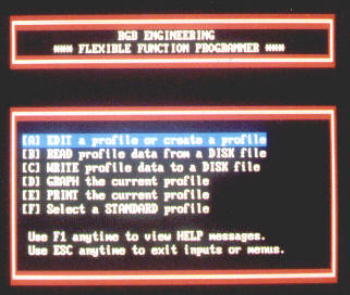
FFP curve generating software and programming routines are designed to be as
user friendly as possible. The photo on the immediate right shows the main menu
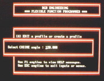
selections for the FFP program. Any portion of a standard truncated sinusoidal
curve can easily be generated by selecting the "F" option, then inputting the
desired shape factor (70 degrees, 120 degrees, etc.), and pressing "Enter". The
photo below left is a reproduction of the computer
 screen
that has graphed a 70 degree profile. This is the same shape that would be
produced by a circular eccentric made to rotate 70 degrees either side of the
roll center. Although
screen
that has graphed a 70 degree profile. This is the same shape that would be
produced by a circular eccentric made to rotate 70 degrees either side of the
roll center. Although the reproduction of these truncated sinusoidal profiles is a simple procedure,
the real benefit of the FFP program is its ability to also generate empirical or
non-mathematical type curves, as for instance, the "bed
correction" curve, backup roll dubbing, compound crowns for paper mill
applications, etc. Since the FFP software forms an x-y table of coordinates, it
is an easy matter to either modify the table, or generate a new x-y table from
scratch. The photo on the right shows a typical x-y table in the edit mode.
Pressing "F3" will clear all the data, and allow the formation of a new curve.
As few as two, or as many as 500 points can be programmed. Two points form a
straight line. Three points generate a perfect parabola. Third order polynomial
curve fitting algorithms are used to interpolate between four or more points, so
that as smooth a curve as possible is always drawn. The "x" values do not have
to be equally spaced, which allows higher density inputs in areas of special
importance, as for instance in a transition zone between a flat an
the reproduction of these truncated sinusoidal profiles is a simple procedure,
the real benefit of the FFP program is its ability to also generate empirical or
non-mathematical type curves, as for instance, the "bed
correction" curve, backup roll dubbing, compound crowns for paper mill
applications, etc. Since the FFP software forms an x-y table of coordinates, it
is an easy matter to either modify the table, or generate a new x-y table from
scratch. The photo on the right shows a typical x-y table in the edit mode.
Pressing "F3" will clear all the data, and allow the formation of a new curve.
As few as two, or as many as 500 points can be programmed. Two points form a
straight line. Three points generate a perfect parabola. Third order polynomial
curve fitting algorithms are used to interpolate between four or more points, so
that as smooth a curve as possible is always drawn. The "x" values do not have
to be equally spaced, which allows higher density inputs in areas of special
importance, as for instance in a transition zone between a flat an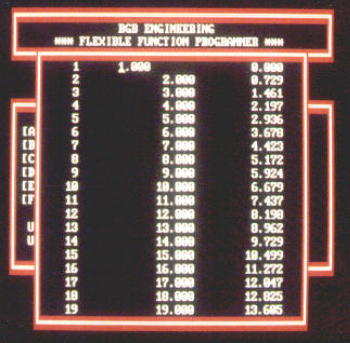 d
curved section. The program will ultimately always convert the data to 500 point
form no matter how many points are used, and any points that were entered in
non-ascending or descending order will be automatically fixed. When inputting
numbers that define a profile, any convenient scale can be used, as long as the
units are consistent. The FFG will automatically normalize the "y" axis to the
amount of crown allocated, and the "TSF" and "TSH" roll end points, which are
entered by the operator, fix the scale along the roll axis. Once the FFP profile
is entered, the "D" command can be used to graph the shape, to make sure the
curve looks correct, and then it can be saved using the "C" command. Once in
memory, it can be recalled at any time using the "B" command in the FFP program.
Pressing "F2" in the FFG setup menu brings up a list of all the stored programs,
so that a selection can be made for the crown profile or bed correction curve.
d
curved section. The program will ultimately always convert the data to 500 point
form no matter how many points are used, and any points that were entered in
non-ascending or descending order will be automatically fixed. When inputting
numbers that define a profile, any convenient scale can be used, as long as the
units are consistent. The FFG will automatically normalize the "y" axis to the
amount of crown allocated, and the "TSF" and "TSH" roll end points, which are
entered by the operator, fix the scale along the roll axis. Once the FFP profile
is entered, the "D" command can be used to graph the shape, to make sure the
curve looks correct, and then it can be saved using the "C" command. Once in
memory, it can be recalled at any time using the "B" command in the FFP program.
Pressing "F2" in the FFG setup menu brings up a list of all the stored programs,
so that a selection can be made for the crown profile or bed correction curve.
One of the popular uses for the FFP program is to create "CVC" profiles, which
are becoming more and more prevalent in the industry. It is not possible to
generate a CVC
curve using a conventional mechanical ecc![]() entric cam type crowning device. This
can only be done using a CNC control, or with a computerized crowner retrofit
like the RGB FFG/FFP/SCA. The sketch on the right shows a typical top and bottom
set of rolls with the CVC contour. The plot below is this same profile as
developed by the RGB FFP program. This was made by simply entering the x-y
coordinates for the CVC curve, as supplied
entric cam type crowning device. This
can only be done using a CNC control, or with a computerized crowner retrofit
like the RGB FFG/FFP/SCA. The sketch on the right shows a typical top and bottom
set of rolls with the CVC contour. The plot below is this same profile as
developed by the RGB FFP program. This was made by simply entering the x-y
coordinates for the CVC curve, as supplied
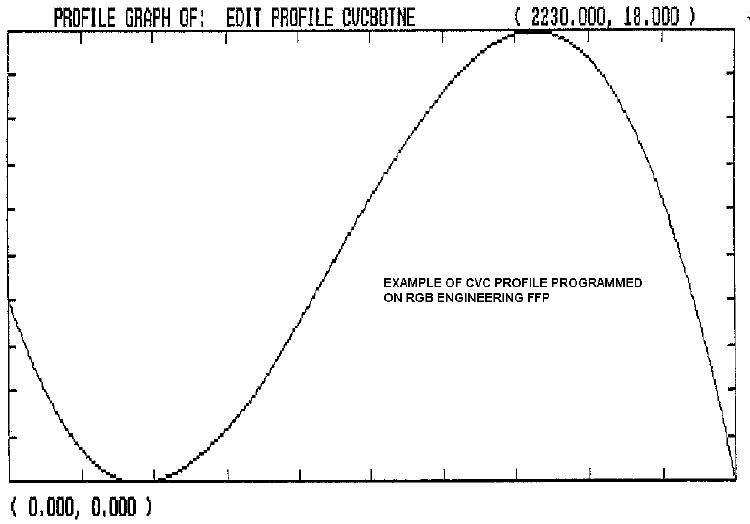 by the roll producer. In addition,
for customers who want the ability to develop the FFP CVC profiles directly from
the mathematical formula, a technique has been developed using
Microsoft Excel to calculate the equation, then transfer the data directly into
the FFP.PFL format. A typical CVC equation is given by the formula:
by the roll producer. In addition,
for customers who want the ability to develop the FFP CVC profiles directly from
the mathematical formula, a technique has been developed using
Microsoft Excel to calculate the equation, then transfer the data directly into
the FFP.PFL format. A typical CVC equation is given by the formula:
y = a1x + a2x2 + a3x3
Using the above method, it is possible to quickly and easily generate new .PFL
profiles by simply changing one or more of the "a" coefficients in the Excel
spreadsheet, then downloading the files to a paste buffer like Notepad, and then
to the FFP using the special program TXTTOPFL.