| Home |
BED CORRECTION FEATURE
COMPUTERIZED CROWNER RETROFIT SYSTEM
Roll Shape Comparison - Effect of Bed Correction Curve
Plot #1 on the right
shows the Pro-Mic record of a hot mill work roll ground in a 1969 vintage 36"
Farrel grinder in a steel mill roll shop. For this test grind, the crowner
system was turned off, allowing the machine
.gif) to
cut the natural "bed" shape into the roll. As can be seen, this is a severely
distorted convex profile. It would be impossible to compensate for this
non-symmetrical shape error using a standard mechanical crown cam.
to
cut the natural "bed" shape into the roll. As can be seen, this is a severely
distorted convex profile. It would be impossible to compensate for this
non-symmetrical shape error using a standard mechanical crown cam.
Plot #2 below is the Pro-Mic shape after grinding the same roll with the RGB
Engineering crowner system runnin![]() g
with the bed correction feature activated. Since the bed correction is
superimposed automatically with the targeted crown curve, the operator simply
sets the desired crown, which in this case was "0" for a flat roll.
g
with the bed correction feature activated. Since the bed correction is
superimposed automatically with the targeted crown curve, the operator simply
sets the desired crown, which in this case was "0" for a flat roll.
Bed Correction Curve - Programming Example
The bed correction
curve is input as an x-y table of values in the FFP program. The "x" values
represent carriage (or table) encoder readings which correspond with marked
station readings on the Pro-Mic plot. For this example, the encoder reading at
station "0" is 81.84 and at station "20" it is 157.13. As many points as
necessary can be selected to properly define the curve. The software has curve
smoothing algorithms that will fit the curve to the points selected. The final
bed correction curve must be continuous for the entire wheel travel, even though
the end sections will probably be outside of the normal grinding area. For these
regions, the curve can be extrapolated as shown below. The "y" ordinates are
obtained from the Pro-Mic plot at each station using any convenient scale. The final scaling is fixed by the "bed
correction factor", input in the Setup menu of the FFG program. This factor is
the largest ordinate distance from the highest point on the curve to the
baseline and must be in radial measurement units.
each station using any convenient scale. The final scaling is fixed by the "bed
correction factor", input in the Setup menu of the FFG program. This factor is
the largest ordinate distance from the highest point on the curve to the
baseline and must be in radial measurement units.
As shown above, it is not unusual to have one or two iterations before the final
bed correction curve is defined. Follow-up checks can be done periodically to
monitor the "flat" roll profiles. Once the technique is established, it is an
easy matter to "tweak" the curve to keep the grinder running at optimum
performance.
Test Grind - Crown Shape
Using the same bed
correction curve from the example above, a test grind was done in this machine
to grind a crown shape with the RGB Engineering FFG/FFP/SCA control. The
results are shown in the Pro-Mic plot reproduced below. The crown height
is slightly less than the target due to the fact that this Pro-Mic does no![]() t
measure all the way to the end of the roll, which is the true end point of the
crown. This crowner retrofit is installed on a 1955 vintage 36" x 16'
Farrel roll grinder in a steel mill cold reduction roll shop. The grinding
was done on an 82" face four stand work roll. As can be seen from the
original test grind without the bed correction, it would be impossible to
produce this accuracy with a manual crowning system due to the unsymmetrical
shape of the bed error. This would have the effect of shifting the apex of
the crown toward the headstock, with a corresponding distorting effect on the
overall shape accuracy.
t
measure all the way to the end of the roll, which is the true end point of the
crown. This crowner retrofit is installed on a 1955 vintage 36" x 16'
Farrel roll grinder in a steel mill cold reduction roll shop. The grinding
was done on an 82" face four stand work roll. As can be seen from the
original test grind without the bed correction, it would be impossible to
produce this accuracy with a manual crowning system due to the unsymmetrical
shape of the bed error. This would have the effect of shifting the apex of
the crown toward the headstock, with a corresponding distorting effect on the
overall shape accuracy.
Example of Bed Correction Superposition
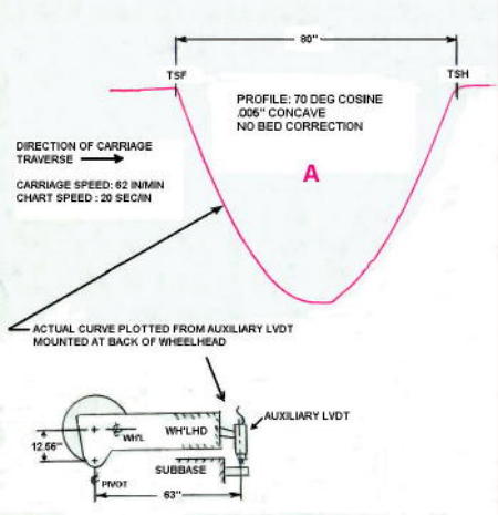
These three plots
were made using an auxiliary LVDT mounted as shown to measure the actual
wheelhead tilt motion. The tests were done on a 1965 vintage Farrel grinder
equipped with the RGB Engineering FFG/FFP/SCA crowner system. Plot "A" on
the top shows the wheelhead motion without the bed correction curve activated,
for a 70 degree profile shape with a .005" concave setting. The roll end limits
"TSH" and "TSF" define the crown axis for the 80" face roll. Plot "B" in the
middle was made with the bed correction curve a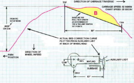 ctivated,
and with a zero crown setting. This curve shows only the inverted bed error,
without any crowning contribution. The TSH and TSF trip points are
overlaid on the plot to indicate the portion of the curve (yellow area) that
will be superimposed with the crown profile. Plot "C" on the bottom was taken
with a .005" concave programmed and with the bed correction curve
ctivated,
and with a zero crown setting. This curve shows only the inverted bed error,
without any crowning contribution. The TSH and TSF trip points are
overlaid on the plot to indicate the portion of the curve (yellow area) that
will be superimposed with the crown profile. Plot "C" on the bottom was taken
with a .005" concave programmed and with the bed correction curve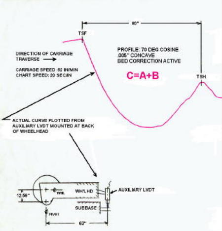 active. This is simply the algebraic sum of plots "A" and "B". The small end
taper (vertical offset between TSH and TSF) will be automatically compensated
for when the operator makes normal taper corrections. As can be seen from this
example, the working portion of the bed correction curve is automatically
selected when the operator sets the TSH and TSF end stops in the FFG setup menu.
active. This is simply the algebraic sum of plots "A" and "B". The small end
taper (vertical offset between TSH and TSF) will be automatically compensated
for when the operator makes normal taper corrections. As can be seen from this
example, the working portion of the bed correction curve is automatically
selected when the operator sets the TSH and TSF end stops in the FFG setup menu.
RGB/Pro-Mic Integration
RGB Engineering and Pro-Mic Corporation are working together to "automate" this bed correction process. This is an ongoing development project in an Aluminum mill roll shop, which has a RGB crowner installed on a Cincinnati TT grinder and a Pro-Mic with modified software . After each final roll shape is skated, the operator initiates a download of the data to a holding file, along with a few key parameters (target crown and end stop settings). After an extended period, these accumulated roll shapes are sent to RGB Engineering for processing in a data base program. Each plot is analyzed and compared to the true target shape, resulting in a "deviation" curve. These are averaged and further processed to produce the final bed correction curve, which is e-mailed to the customer and then installed in the FFG replacing the original bed curve.
After sufficient testing, the plan is to establish a hard-wired connection between the Pro-Mic computer and the RGB FFG crowner which will essentially automate the complete bed correction process. This will then be a form of true "adaptive" control, since the grinder will always be programming itself to continuously optimize the roll shapes, without operator intervention. This simplified form of adaptive control is a much less expensive option compared with the newer style CNC grinders with in-process calipers.