INSTALLATION EXAMPLES: MESTA - LATER DESIGN ROLL GRINDER
COMPUTERIZED CROWNER RETROFIT SYSTEM
RGB Engineering has also retrofitted the later design Mesta roll grinders with the FFG/FFP/SLA computerized crowner retrofit system. This class of Mesta grinders are of the more conventional type with an independent wheel motor belt driving the spindle. However, the mechanical cam type crowning device is radically different, making it more restrictive than the classical adjustable eccentric cams found on most roll grinders.
A pinion attached to the bottom of a vertical worm shaft engages the traverse rack which is bolted to the inside edge of the back bed cavity. This drive pinion can be mechanically clutched in and out of engagement with the rack, by means of a lever arrangement accessible to the operator on the carriage platform. The worm meshes with a worm gear (5.167:1 ratio), on a horizontal stub shaft 90 degrees to the vertical worm shaft. a 30 tooth spur gear, mounted next to the worm gear on the same stub shaft, engages a long mating 24 tooth idler gear at a 45 degree angle on a parallel shaft. This idler gear and worm assembly are mounted on the grinder carriage. There is another parallel shaft attached to the cross feed slide base vertically above the idler gear, which is integral with the eccentric. A 40 tooth spur gear on the inboard end of this shaft meshes with the idler gear. This gear translates along the idler gear as the cross slide moves in and out. Therefore, as the carriage traverses along the bed, the cam rotates.
The "cam" is really not a cam in the true sense, but rather an eccentric which is offset a specific amount from the true center of rotation. The Mesta design differs from most other grinders in that this is a fixed eccentricity (.5" for this example), machined into the shaft. Other grinders employ an adjustable eccentric for setting the total throw of the cam, and thus controlling the magnitude of the crown. The Mesta design accomplishes this using a secondary lever which rides the cam follower assembly. The "ratio" of the lever is adjustable using a rack and pinion arrangement that moves the actuation point relative to the pivot center. A graduated dial is provided that calibrates the adjustment as a function of the crown height and roll face length.
For
this Mesta design, there is a secondary tilt infeed axis which mechanically
superimposes a tilt feed with the crown portion of the infeed. This is
accomplished using another eccentric lever which operates in series with the
crown input. This can be actuated through a mechanical handwheel or a DC
motor. The output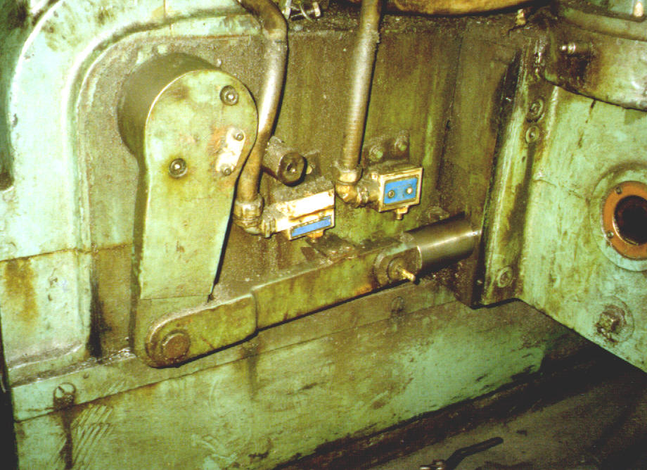 of the motor/handwheel drives an 80:1 worm, which in turn operates through a 3:1
spur gear reduction to turn a 2.25" PD pinion engaging a rack. The
translation of the rack moves an 8" lever arm on the .75" eccentric. The
pivoting action of this eccentric arm works in conjunction with the crowning
motion, and is imparted to the grinding wheel through the tilting action of the
camber base, which pivots about a trunnion bearing directly under the wheel
centerline. The crowning and tilt motion, then, are superimposed with the
normal wheel slide infeed as controlled by the operator. The camber base
pivots on the cross feed base, which slides on top of the carriage. The
photo above shows a portion of the secondary tilt infeed mechanism on the side
of the wheelhead as it existed before the crowner retrofit upgrade.
of the motor/handwheel drives an 80:1 worm, which in turn operates through a 3:1
spur gear reduction to turn a 2.25" PD pinion engaging a rack. The
translation of the rack moves an 8" lever arm on the .75" eccentric. The
pivoting action of this eccentric arm works in conjunction with the crowning
motion, and is imparted to the grinding wheel through the tilting action of the
camber base, which pivots about a trunnion bearing directly under the wheel
centerline. The crowning and tilt motion, then, are superimposed with the
normal wheel slide infeed as controlled by the operator. The camber base
pivots on the cross feed base, which slides on top of the carriage. The
photo above shows a portion of the secondary tilt infeed mechanism on the side
of the wheelhead as it existed before the crowner retrofit upgrade.
It is important to recognize that the crown shapes that can be produced from this kind of bellcrank eccentric are sinusoidal in nature, since the principles of simple harmonic motion apply. Actually, this Mesta design restricts the roll profile to a specific angle, which is a function of the roll face length. On most of the other more conventional grinders, it is a simple matter to vary the cosine angle by using different combinations of change gears. But since there are no change gears with this Mesta design, the "shape" of the crown curve is dependent on the length of roll to be ground. With today's roll shop varied shape requirements, this is a severe limitation.
The RGB FFG/FFP/SLA crowner retrofit addresses this issue, by retaining the basic elements of the proven tilting wheelhead concept, and using a DC servo motor to operate through a double timing belt reduction to the "tilt infeed" portion of the Mesta drive mechanism. the crowning portion of the Mesta eccentric infeed is disabled by locking out the engagement clutch. The original Mesta tilt infeed motor and handwheel are removed (also required to provide clearance for a new wheel motor on this job). One of the inherent advantages of the new SLA crowner design is that the original Mesta mechanical crowning device can be easily activated by reengaging the clutch, if ever required for emergency operation.
The new
Servo Linear Actuator (SLA) is combined with a state of the art computer system
(FFG) and customized software (FFP) for producing any desired roll shape.
The sketch below shows the new SLA drive arrangement in schematic fashion.
The existing drive train is essentially decoupled by disengaging the mechanical
clutch, and removing the tilt motor and handwheel. As described above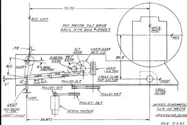 , the
DC servo motor operates through a double timing belt reduction to rotate the
ball screw and actuate the existing eccentric tilt infeed portion of the Mesta
drive mechanism. Carriage position is monitored using a multi-turn
absolute encoder connected through appropriate belting to engage the existing
Mesta reversing control heli-pot gear drive train. This feeds a digital
display output on the computer as well as producing the signals for the "x" axis
of the crown profile. The command signals are produced by the FFG, which
is located in a floor mounted enclosure off the carriage. The FFG receives
digital inputs from the absolute encoder, and produces digital profiles from the
FFP resident software. The outputs go through a D/A board, then into
summing circuits to command the servo motor for "y" axis positioning. To
minimize backlash and lost motion, a LVDT is mounted on the back of the
wheelhead to measure the crowning action directly, taking into account the
magnification effect due to the pivot ratio. This then forms the linear
feedback to complete the positioning servo loop.
, the
DC servo motor operates through a double timing belt reduction to rotate the
ball screw and actuate the existing eccentric tilt infeed portion of the Mesta
drive mechanism. Carriage position is monitored using a multi-turn
absolute encoder connected through appropriate belting to engage the existing
Mesta reversing control heli-pot gear drive train. This feeds a digital
display output on the computer as well as producing the signals for the "x" axis
of the crown profile. The command signals are produced by the FFG, which
is located in a floor mounted enclosure off the carriage. The FFG receives
digital inputs from the absolute encoder, and produces digital profiles from the
FFP resident software. The outputs go through a D/A board, then into
summing circuits to command the servo motor for "y" axis positioning. To
minimize backlash and lost motion, a LVDT is mounted on the back of the
wheelhead to measure the crowning action directly, taking into account the
magnification effect due to the pivot ratio. This then forms the linear
feedback to complete the positioning servo loop.