INSTALLATION EXAMPLES: LANDIS TT ROLL GRINDER, Z-MILL
COMPUTERIZED CROWNER RETROFIT SYSTEM
This Landis type F 16" x 72" traveling table roll grinder was purchased used by a producer of specialty steel to grind the work rolls and intermediate rolls of a Sendzimir mill. The intermediate rolls in particular have unique shape requirements. Essentially, what this entails is a straight section on one end intersecting a straight taper on the opposite end, with a special contoured radius at the intersection point. This transition shape from flat to taper is very critical, being defined by Sendzimir as an empirical curve which cannot be ground with the conventional mechanical type crowning device as originally supplied on this grinder. Rather than purchase new CNC equipment, the customer elected to upgrade the existing grinder with a computerized FFG/FFP/SCA crowner supplied by RGB Engineering.
The sc hematic
below shows the arrangement of the standard crowning device before the retrofit.
A crown drive rack is attached to the traveling table (work carriage). A
pinion meshing with the rack engages a set of gears on the idler shaft, which in
turn drive a pinion on the input change gear shaft. A helical gear on the
output change gear shaft transfers the motion to a right angle worm gear shaft.
This worm meshes with a worm gear integral with the rotating cam assembly.
Therefore, as the table traverses along the bed, the cam rotates.
hematic
below shows the arrangement of the standard crowning device before the retrofit.
A crown drive rack is attached to the traveling table (work carriage). A
pinion meshing with the rack engages a set of gears on the idler shaft, which in
turn drive a pinion on the input change gear shaft. A helical gear on the
output change gear shaft transfers the motion to a right angle worm gear shaft.
This worm meshes with a worm gear integral with the rotating cam assembly.
Therefore, as the table traverses along the bed, the cam rotates.
The cam is really not a cam in the true sense, but rather an eccentric which is offset a specific amount from the true center of rotation. A cam follower, set in a slide member, rides the eccentric, and is made to translate vertically as the cam rotates.
This
crowning motion is imparted to the grinding wheel through the tilting wheelhead
ca mbering syste
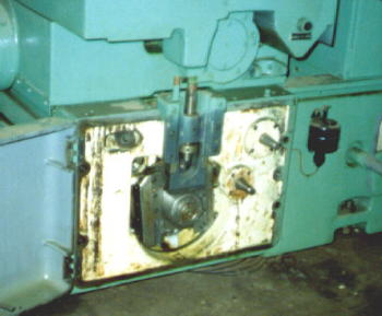 m, which consists of a simple trunnion pivot arrangement, with
support points at the two front pivots and
the center mounted cam follower bearing at the rear. Mechanical
superposition of the crown input with the normal handwheel slide infeed is
achieved with this system. The normal wheel infeed occurs
between the camber base and the upper slide member. The photos above show
the rear view of the wheelhead and mechanical crowning device as it existed
before the retrofit.
m, which consists of a simple trunnion pivot arrangement, with
support points at the two front pivots and
the center mounted cam follower bearing at the rear. Mechanical
superposition of the crown input with the normal handwheel slide infeed is
achieved with this system. The normal wheel infeed occurs
between the camber base and the upper slide member. The photos above show
the rear view of the wheelhead and mechanical crowning device as it existed
before the retrofit.
It is important to recognize that the crown shapes that can be produced from this kind of bellcrank eccentric are sinusoidal in nature, since the principles of simple harmonic motion apply. It is a simple matter to vary this shape to other cosine angles by using different combinations of change gears. A chart is provided to select the appropriate change gears for a particular roll face and angle of cam rotation. But no matter what combinations of gears are used, the crown will always be a portion of a cosine curve. The amount of crown is controlled by fixing the total offset of the cam through the vernier adjustment built into the cam mechanism. The crown charts tabulate these offsets or eccentricity as a function of the required crown.
This mechanical system as described has the advantage of simplistic operation, but is limited to the development of pure sinusoidal crown shapes only. The special Z-mill roll contours could not be ground with this mechanism. The RGB Engineering FFG/FFP/SCA crowner retrofit addresses this issue, by retaining the basic elements of the proven cam type system for actuating the camber tilt infeed (SCA), and combining it with a state of the art computer system (FFG) and customized software (FFP) for producing any desired roll shape.
The SCA
accomplishes these objectives by using the existing eccentric cam with a preset
offset to actuate the wheelhead camber tilt system in the conventional manner.
The sketch below shows the new operational schematic. The existing drive
train is essentially decoupled at the change gear interface.
On what was the "driven" change gear shaft, a DC servo motor operates through a
harmonic drive reducer and timing belt connection into the conventional gear
train to produce cam rotation. Carriage position is monitored using a
multi-turn absolute encoder connected through appropriate belting to the input
change gear shaft. This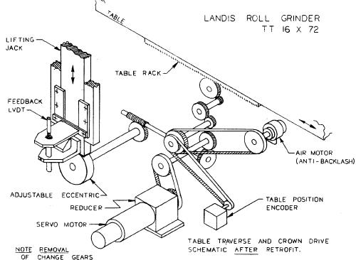 feeds a digital display output on the computer as
well as producing the signals for the "x" axis of the crown profile. A
belt connected air motor is used to eliminate the backlash in the existing crown
drive gear train. (Subsequent to this installation, RGB Engineering has
developed software "backlash compensation", which accomplishes the same results
at less cost.)
feeds a digital display output on the computer as
well as producing the signals for the "x" axis of the crown profile. A
belt connected air motor is used to eliminate the backlash in the existing crown
drive gear train. (Subsequent to this installation, RGB Engineering has
developed software "backlash compensation", which accomplishes the same results
at less cost.)
The command signals are produced by the FFG, which is located in a floor mounted enclosure near the operator's station. The FFG receives digital inputs from the absolute encoder, and produces digital profiles from the FFP resident software. This includes a conversion program to convert the special Sendzimir shape profiles to FFP format. The outputs go through a D/A board, then into summing circuits to command the servo motor for "y" axis positioning. Since the crown actuator is a non-linear device, a LVDT is mounted on the back of the wheelhead to measure the crowning action directly, taking into account the magnification effect due to the pivot ratio. This then forms the linear feedback to complete the positioning servo loop.