INSTALLATION EXAMPLES: LANDIS TT ROLL GRINDER, TYPE B
COMPUTERIZED CROWNER RETROFIT SYSTEM
This was a rather unique situation, where damage sustained to a Landis 28" hydraulic traveling table roll grinder had made the crowning device inoperable. What made the situation even worse was the age of the grinder, and the exclusivity of the crowner design, which included a "double cam" type eccentric actuator. Due to the fact that OEM replacement parts were essentially non-existent, and the timeframe for rehabilitating the grinder was critical, this customer elected to upgrade to the RGB Engineering computerized crowner retrofit rather than try to repair the antiquated equipment.
The p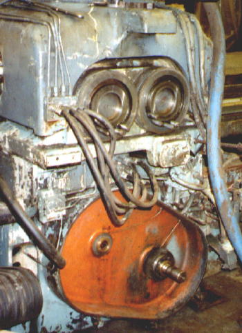 hoto
below shows the back of the grinder as it existed before the crowner retrofit.
The double cams have been removed to expose the machined mounting surface for
the new SLA crowner actuator. A pinion meshing with the table traverse
rack on the front bed connects through an idler gear to a power take off shaft,
which extends full length from the front bed to the back of the subbase.
This shaft meshes with appropriate gearing to rotate the "drive" change gear
shaft, which is parallel to the "driven" change gear shaft. The rotary
motion is transferred through a series of bevel gears and a spline shaft to the
upper infeed slide (subbase), on which the double cam (eccentric) mechanism is
mounted. The final drive to the two eccentrics is through worms and worm
gears. Therefore, as the table traverses along the bed, the cams rotate.
Since there are a number of gear meshes between the table traverse rack and the
cam, and since spur gears and worm gears have inherent backlash, the design
includes a backlash compensation mechanism to eliminate the backlash and lost
motion of this gear train.
hoto
below shows the back of the grinder as it existed before the crowner retrofit.
The double cams have been removed to expose the machined mounting surface for
the new SLA crowner actuator. A pinion meshing with the table traverse
rack on the front bed connects through an idler gear to a power take off shaft,
which extends full length from the front bed to the back of the subbase.
This shaft meshes with appropriate gearing to rotate the "drive" change gear
shaft, which is parallel to the "driven" change gear shaft. The rotary
motion is transferred through a series of bevel gears and a spline shaft to the
upper infeed slide (subbase), on which the double cam (eccentric) mechanism is
mounted. The final drive to the two eccentrics is through worms and worm
gears. Therefore, as the table traverses along the bed, the cams rotate.
Since there are a number of gear meshes between the table traverse rack and the
cam, and since spur gears and worm gears have inherent backlash, the design
includes a backlash compensation mechanism to eliminate the backlash and lost
motion of this gear train.
Each "cam" is really not a cam in the true sense, but rather an eccentric which is offset a specific amount from the true center of rotation. The individual motions are superimposed via a linkage mechanism to a cam follower, which lifts the wheelhead. This crowning motion is imparted to the grinding wheel through the tilting action of the wheelhead, which pivots about a trunnion bearing at the front. The crowning motion, then, is superimposed with the normal wheel slide infeed as controlled by the operator. The slide ways are between the back bed and the subbase, which maintains a constant geometric relationship between the wheel and pivot centerlines (this is the preferred design, compared to some machines where the slideways are above the pivot point).
It is important to recognize that the crown shapes that can be produced from this kind of bellcrank eccentric are sinusoidal in nature, since the principles of simple harmonic motion apply. It is possible to vary this shape to other cosine angles by using different combinations of change gears. However, for this style of Landis grinder, it was not the intention to maintain a constant 70 degree shape. The gears were selected primarily to facilitate the magnitude of the crown, in conjunction with the eccentricity adjustments on the cams. Therefore, there are two inherent limitations with this original mechanical crowning arrangement:
1. No matter what combinations of gears are used, the crown will always be a portion of a cosine curve.
2. The roll "shape" will probably be different for each roll length (roll shape refers to the truncated portion of the cosine curve for the face length being ground).
The above notwithstanding, this mechanical system as described has served the industry well over the years. Its main attribute is simplicity of operation which has made it a reliable and accurate method of producing crown shapes. However, as noted above, it is limited to the development of pure sinusoidal shapes only. More importantly, for this installation example, due to the severe mechanical damage sustained to the critical crown drive components in the aforementioned accident, the cost to repair this drive train approached the cost of the computerized crowner retrofit. Luckily, tests showed that the action of the wheelhead tilt system was still very accurate and repeatable.
The FFG/FFP/SLA crowner retrofit addresses this issue, by retaining the basic elements of the proven tilting wheelhead, and replacing the damaged cam drive assembly with a new direct acting ball screw actuator that engages the wheelhead at the same point as the old cam follower bearing. Also, the ball screw actuator is designed for positive action due to its minimized backlash combined with the gravity preload effect. This Servo Linear Actuator (SLA) is combined with a state of the art computer system (FFG) and customized software (FFP) for producing any desired roll shape.
The sketch
below shows the new infeed schematic. The existing drive train is
essentially decoupled at the change gear interface. As described above,
the DC servo motor operates through a harmonic drive reducer and timin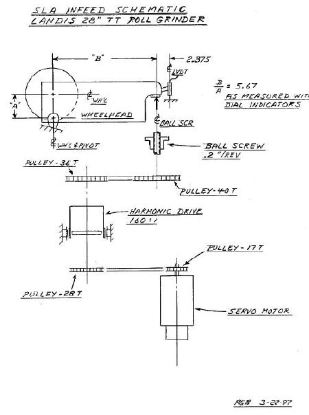 g belt
reduction to rotate the ball screw and actuate the existing wheelhead.
Table position is monitored using a multi-turn absolute encoder connected
through appropriate belting to engage the original "drive" change gear shaft.
This feeds a digital display output on the computer as well as producing the
signals for the "x" axis of the crown profile. The command signals are
produced by the FFG, which is located in a floor mounted enclosure near the
existing operator's station in front of the grinder. An IBM compatible
industrial computer interfaces through an A/D board and other peripheral devices
to provide the outputs to the SLA. The FFG receives digital inputs from
the absolute encoder, and produces digital profiles from the FFP resident
software. The outputs go through a D/A board, then into summing circuits
to command the servo motor for "y" axis positioning. To minimize backlash
and
g belt
reduction to rotate the ball screw and actuate the existing wheelhead.
Table position is monitored using a multi-turn absolute encoder connected
through appropriate belting to engage the original "drive" change gear shaft.
This feeds a digital display output on the computer as well as producing the
signals for the "x" axis of the crown profile. The command signals are
produced by the FFG, which is located in a floor mounted enclosure near the
existing operator's station in front of the grinder. An IBM compatible
industrial computer interfaces through an A/D board and other peripheral devices
to provide the outputs to the SLA. The FFG receives digital inputs from
the absolute encoder, and produces digital profiles from the FFP resident
software. The outputs go through a D/A board, then into summing circuits
to command the servo motor for "y" axis positioning. To minimize backlash
and
 lost
motion, a LVDT is mounted on the back of the wheelhead to measure the crowning
action directly, taking into account the magnification effect due to the pivot
ratio. This then forms the linear feedback to complete the positioning
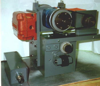
servo loop. The photo on the right shows the SLA unit, preassembled for
bench testing before shipment.
lost
motion, a LVDT is mounted on the back of the wheelhead to measure the crowning
action directly, taking into account the magnification effect due to the pivot
ratio. This then forms the linear feedback to complete the positioning
servo loop. The photo on the right shows the SLA unit, preassembled for
bench testing before shipment.
This customer elected to purchase a number of options in addition to the basic crowner control with bed correction. These included taper control, precision infeed with the handwheel option, continuous & end infeeds, a table speed indicator, and the trip switch safety feature. Since the original damage to the mechanical crowning device was a result of the table running through the end stops, as an enhancement for increased protection, the updated revised control logic uses the new crowner TSF & TSH software trip switches for reversing control, with the mechanical limits utilized as redundant safety trips. The optional trip switch safety feature includes a watchdog timer and other safeguards to insure maximum protection against a trip switch failure.