INSTALLATION EXAMPLES: FARREL TT ROLL GRINDER
COMPUTERIZED CROWNER RETROFIT SYSTEM
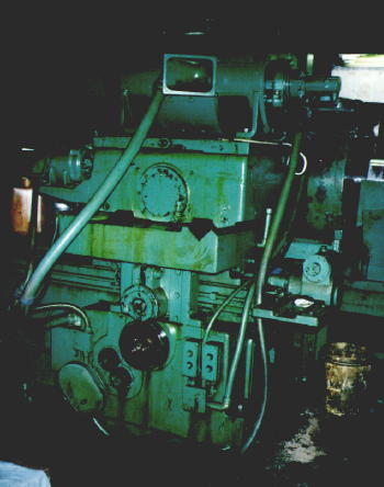
This 32" x 12' 1942 vintage Farrel traveling table roll grinder was equipped with a mechanical cam type crowning device for grinding only sinusoidal shapes on the roll bodies. It was upgraded to the RGB computerized crowner retrofit in 1991. For this customer, the primary justification for the conversion was the improvement in accuracy resulting from the precision infeed handwheel enhancement, eliminating the chronic stick-slip and backlash problems associated with the old slide-way infeed system.
The
schematic and photo on the right show the machine configuration before the
retrofit. The existing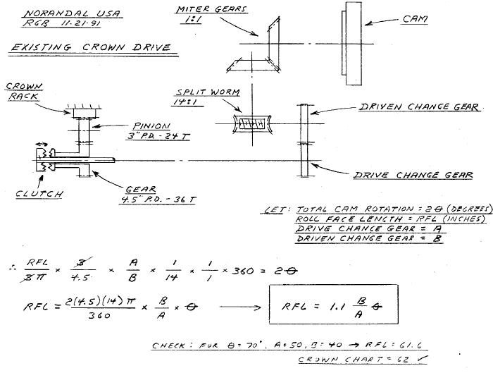 crown cam is driven from an 8 DP rack bolted to the
underside of the traveling table. A 24 tooth 3"
pitch diameter pinion meshes with the rack, and also with a 36 tooth 4-1/2"
pitch diameter spur gear, which is mounted on the front side of connecting drive
shaft through a mechanical clutch arrangement. The clutch can be manually
disengaged by the operator when it is necessary to disconnect the cam from the
drive train. This drive shaft is coupled to the back bed drive shaft at
the
crown cam is driven from an 8 DP rack bolted to the
underside of the traveling table. A 24 tooth 3"
pitch diameter pinion meshes with the rack, and also with a 36 tooth 4-1/2"
pitch diameter spur gear, which is mounted on the front side of connecting drive
shaft through a mechanical clutch arrangement. The clutch can be manually
disengaged by the operator when it is necessary to disconnect the cam from the
drive train. This drive shaft is coupled to the back bed drive shaft at
the
 joint interface. The input, or "drive" change gear mounts on the
exposed end of this shaft which extends out the end of the back bed. The
"driven" change gear is attached to the
end of a short parallel shaft. On the inboard end of this shaft, a 14:1
split worm gear transfers the motion to a vertical stub shaft. Miter gears
connect at right angles to the horizontal cam shaft. Therefore, as the
table traverses along the bed, the cam rotates.
joint interface. The input, or "drive" change gear mounts on the
exposed end of this shaft which extends out the end of the back bed. The
"driven" change gear is attached to the
end of a short parallel shaft. On the inboard end of this shaft, a 14:1
split worm gear transfers the motion to a vertical stub shaft. Miter gears
connect at right angles to the horizontal cam shaft. Therefore, as the
table traverses along the bed, the cam rotates.
The "cam" is really not a cam in the true sense, but rather an eccentric which is offset a specific amount from the true center of rotation. A cam follower bearing, supported in a vertical slide, rides the eccentric, and imparts this crowning motion to the back of the subbase. The final mechanical advantage is achieved through the tilting subbase. This consists of a simple trunnion pivot arrangement, with support points at the two front pivots and the center mounted follower bearing engaging the cam at the rear. Mechanical superposition of the crown input with the normal handwheel slide infeed is achieved with this system. The normal wheel infeed occurs between the camber base (subbase) and the upper slide member (wheelhead), as shown in the above photo.
The amount of crown is controlled by fixing the total offset of the cam through the vernier adjustment built into the cam mechanism. The Farrel crown charts tabulate these offsets or eccentricity as a function of the required crown.
The original grinder was equipped with a translating upper carriage on the back bed, which was used for grinding tapers on the roll necks and journals. This has been disconnected and is not used.
The
s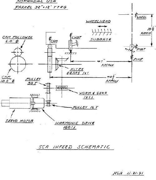 chematic below shows the same machine upgraded with the RGB computerized
crowner retrofit SCA (Servo Cam Actuator) assembly. The existing drive
train is essentially decoupled at the change gear interface.
On what was the "driven" change gear shaft, a DC servo motor operates through a
harmonic drive unit and timing belt reduction into the conventional gear train
to produce cam rotation.
chematic below shows the same machine upgraded with the RGB computerized
crowner retrofit SCA (Servo Cam Actuator) assembly. The existing drive
train is essentially decoupled at the change gear interface.
On what was the "driven" change gear shaft, a DC servo motor operates through a
harmonic drive unit and timing belt reduction into the conventional gear train
to produce cam rotation.
Table position is monitored using a multi-turn absolute encoder connected through appropriate belting to the input change gear shaft to engage the existing drive train gearing. This feeds a digital display on the computer, as well as producing the signals for the "x" axis of the crown profile.
The cam is offset a specific amount, determined at startup for optimized performance. There are no further adjustments required to the cam. With this fixed eccentricity, the wheel infeed can be controlled very accurately with the servo motor. Since the crown actuator is a non-linear device, a LVDT is mounted on the back of the wheelhead to measure the crowning action directly, taking into account the magnification effect due to the pivot ratio. This then forms the linear feedback to complete the positioning servo loop.