INSTALLATION EXAMPLES: FARREL TILT INFEED - POST 1959 VINTAGE ROLL GRINDER
COMPUTERIZED CROWNER RETROFIT SYSTEM
The
schematic representation below shows the classical Farrel tilt infeed system in
blue, together with the new parts required for the retrofit crowner in red.
Using a novel approach, the computerized equipment interf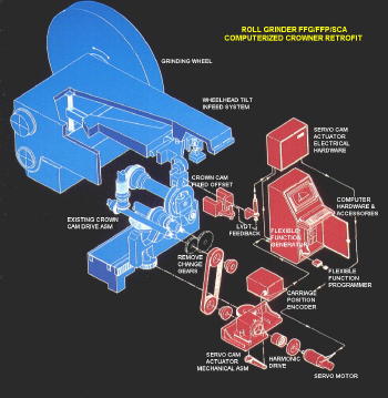 aces
with the existing mechanical crowning system through the change gear input.
The cam is still used, with a fixed offset, to actuate the mechanical crown axis
in the conventional manner. Instead of the cam being driven directly from
the crown rack, it is controlled via a DC servo motor, which is commanded from
the FFG computer in conjunction with the LVDT feedback signal.
aces
with the existing mechanical crowning system through the change gear input.
The cam is still used, with a fixed offset, to actuate the mechanical crown axis
in the conventional manner. Instead of the cam being driven directly from
the crown rack, it is controlled via a DC servo motor, which is commanded from
the FFG computer in conjunction with the LVDT feedback signal.
Farrel developed the tilt infeed wheelhead around 1960. All single wheel machines after this time utilized this design, which consisted of a compound lever arrangement, superimposing both crown control and normal handwheel feed through the same pivoting wheelhead structure. The photos below show a Farrel tilt infeed machine retrofitted with the RGB Engineering FFG/FFP/SCA crowner assembly. As depicted in the schematic above, the SCA assembly is coupled to the existing crown drive gear train using a conventional timing belt connected to the "driven" change gear shaft. The cam is offset a fixed amount (which is a function of the maximum crown and infeed requirements), and set up so that it rotates in two quadrants, from 0 to 180 degrees. A DC servo motor operates through a harmonic drive reducer and the timing belt connection to rotate the cam through the conventional gear train. Therefore, depending on the direction of motor rotation, the wheel will be moved "in" or "out" as the cam rotates to pivot the wheelhead about the trunnion axis.
Since the cam output is nonlinear, a LVDT transducer is mounted in such a way as to measure the cam follower displacement directly. This provides a linear feedback to complete the servo loop. One very important feature that distinguishes the RGB crowner from other systems is the LVDT feedback concept. Instead of using resolvers at the point of actuation (i.e.: on the motor), which is the conventional approach with CNC controls, the objective with the RGB SCA and SLA systems is to locate the feedback transducer (LVDT) as close to the actual wheel motion as possible. By measuring the tilting motion of the wheelhead directly, any backlash or lost motion of "upstream" components (such as gear meshes, key fits, shaft windup, etc.) is automatically eliminated.
An absolute encoder is belt and gear driven
directly from the crown rack pinion, to provide the carriage position inpu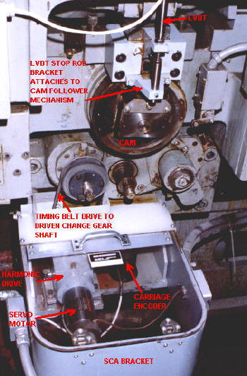 t to
the FFG com
t to
the FFG com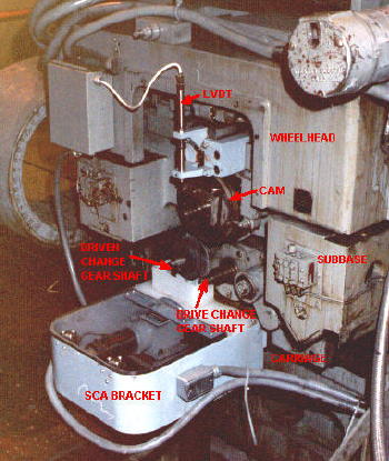 puter. Using the software routines developed for crowning, bed
correction, taper control, etc., the FFG outputs a 0 to 10 volt signal to the
crowner summing board (in the SCA control cabinet), which compares this with the
LVDT feedback voltage, and outputs a voltage reference to the servo motor drive.
As this all happens at computer speed, the result is a wheel path that follows
very closely the theoretical target curves produced by the FFG. A SCA
monitor continuously displays the difference between the FFG target value and the LVDT feedback, which is a direct indication of system accuracy, as well as a
useful diagnostic tool. As can be seen from the above photographs, since
the conventional crown drive train is not disturbed, it would be a simple matter
to remove the timing belt and reinstall the change gears to revert back to
conventional crowning, should it be required in an emergency. The above
crowning arrangement has been retrofitted on a number of Farrel tilt infeed
vintage roll grinders by RGB Engineering. See the customer reference list
for more detail.
puter. Using the software routines developed for crowning, bed
correction, taper control, etc., the FFG outputs a 0 to 10 volt signal to the
crowner summing board (in the SCA control cabinet), which compares this with the
LVDT feedback voltage, and outputs a voltage reference to the servo motor drive.
As this all happens at computer speed, the result is a wheel path that follows
very closely the theoretical target curves produced by the FFG. A SCA
monitor continuously displays the difference between the FFG target value and the LVDT feedback, which is a direct indication of system accuracy, as well as a
useful diagnostic tool. As can be seen from the above photographs, since
the conventional crown drive train is not disturbed, it would be a simple matter
to remove the timing belt and reinstall the change gears to revert back to
conventional crowning, should it be required in an emergency. The above
crowning arrangement has been retrofitted on a number of Farrel tilt infeed
vintage roll grinders by RGB Engineering. See the customer reference list
for more detail.