INSTALLATION EXAMPLES: FARREL 20" x 120" SPECIAL ROLL GRINDER
COMPUTERIZED CROWNER RETROFIT SYSTEM
This
Farrel 1952 vintage 20" traveling carriage grinder was purchased by a steel mill in India in 1995 specifically
for grinding CVC rolls in their revamped rolling mill. CVC technology
requires that a pair of work rolls be ground with opposing
"Coke" bottle shapes, as shown in the adjacent sketch. This non-sinusoidal
profile could![]() not be ground with the original mechanical eccentric cam type
crowning device. RGB Engineering was sub-contracted by Metal Manufacturing
Company to upgrade the grinder with a computerize crowning system as part of
their complete grinder reconditioning project. This customer concluded
that reconditioning a used grinder with the RGB crowner retrofit was much more
cost effective than purchasing a new CNC grinder, which would be the only
other alternative for grinding the CVC rolls.
not be ground with the original mechanical eccentric cam type
crowning device. RGB Engineering was sub-contracted by Metal Manufacturing
Company to upgrade the grinder with a computerize crowning system as part of
their complete grinder reconditioning project. This customer concluded
that reconditioning a used grinder with the RGB crowner retrofit was much more
cost effective than purchasing a new CNC grinder, which would be the only
other alternative for grinding the CVC rolls.
The existing crown cam is driven from an 8 DP rack bolted to the side of the back bed. A pinion meshing with the rack is attached to the bottom end of the input or "drive" change gear shaft. The output or "driven" change gear mounts on a parallel vertical shaft, on which is mounted a worm. A 34 tooth worm gear meshes with the double threaded worm (ratio = 17:1), and transfers the motion through a horizontal cross shaft and two sets of miter gears to the cam shaft. Therefore, as the carriage traverses along the bed, the cam rotates.
As wit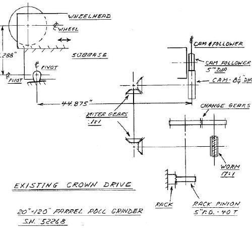 h
most cam type crowning devices, the "cam" is really not a cam in the true sense,
but rather an eccentric which is offset a specific amount from the true center
of rotation. A cam follower attached to the pivoting subbase rides the
eccentric, and imparts this crowning motion to the grinding wheel through the
tilting wheelhead cambering system. This consists of a simple trunnion
pivot arrangement, with support points at the two front pivots and the center
mounted cam follower bearing at the rear. Mechanical
h
most cam type crowning devices, the "cam" is really not a cam in the true sense,
but rather an eccentric which is offset a specific amount from the true center
of rotation. A cam follower attached to the pivoting subbase rides the
eccentric, and imparts this crowning motion to the grinding wheel through the
tilting wheelhead cambering system. This consists of a simple trunnion
pivot arrangement, with support points at the two front pivots and the center
mounted cam follower bearing at the rear. Mechanical
 superposition
of the crown input with the normal handwheel slide infeed is achieved with this
system. The normal wheel infeed occurs between the camber base and the
upper slide member. See the sketch and photo on the left which show the
arrangement before the crowner retrofit.
superposition
of the crown input with the normal handwheel slide infeed is achieved with this
system. The normal wheel infeed occurs between the camber base and the
upper slide member. See the sketch and photo on the left which show the
arrangement before the crowner retrofit.
The
sketch on the right shows the revised schematic depicting the new crowner
retrofit system. The existing drive train is essentially decoupled at the
change gear interface. On what was the drive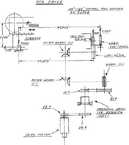 n change gear shaft, a DC
servo motor operates through a harmonic drive reducer and timing belt reductions
into the conventional gear train to produce cam rotation. Carriage
position is monitored using a multi-turn absolute encoder connected through
appropriate gearing to the rack and pinion drive on the side of the back bed.
This feeds a digital display output on the computer as well as producing the "x"
axis of the crown profile. The cam is offset a specific amount, determined
at startup for optimized performance. There are no further adjustments
required to the cam. With this fixed eccentricity, the wheel infeed can be
controlled very accurately with the servo motor. Since the crown actuator
is a non-linear device, a LVDT is mounted on the back of the wheelhead to
measure the crowning action directly, taking into account the magnification
effect due to the pivot ratio. This then forms the linear feedback to
complete the positioning servo loop.
n change gear shaft, a DC
servo motor operates through a harmonic drive reducer and timing belt reductions
into the conventional gear train to produce cam rotation. Carriage
position is monitored using a multi-turn absolute encoder connected through
appropriate gearing to the rack and pinion drive on the side of the back bed.
This feeds a digital display output on the computer as well as producing the "x"
axis of the crown profile. The cam is offset a specific amount, determined
at startup for optimized performance. There are no further adjustments
required to the cam. With this fixed eccentricity, the wheel infeed can be
controlled very accurately with the servo motor. Since the crown actuator
is a non-linear device, a LVDT is mounted on the back of the wheelhead to
measure the crowning action directly, taking into account the magnification
effect due to the pivot ratio. This then forms the linear feedback to
complete the positioning servo loop.
The CVC roll contour is input to the FFP program using an Excel routine as developed specifically for this function. All that is required is to input the CVC third order polynomial coefficients a1, a2, and a3 from the general equation y = a1x + a2x2 + a3x3, and a length factor for the specific roll. Conversion programs resident with the FFP convert the Excel data to readable FFP programs, which in turn condition the curves for the FFG software in the conventional manner. See the section on "FFP Profiles" for more information concerning the FFP program.