COARSE INFEED OPTION
COMPUTERIZED CROWNER RETROFIT SYSTEM
The purpose of "coarse infeed" is to provide a means of automatically feeding the wheel large amounts during heavy grinding cuts, or for prolonged periods of roughing. The "precision infeed" addition to the RGB FFG crown control provides essentially the same benefits, but cannot be used for large amounts of infeed due to the limited tilt range. Conversely, the coarse infeed, which operates through the cross slide ball screw, has, for all practical purposes, an unlimited amount of travel. However, due to the "stick-slip" type of feed, and the inherent backlash of this coarse infeed axis, it should not be used for semi-finish or finish grinding. Therefore, an ideal solution is to combine both of these systems in one control to give the operator maximum flexibility to rough and finish grind the roll as quickly as possible.
The sketch
below shows a typical coarse infeed schematic as applied to a Mesta
grinder. Basically, this design consis ts of a harmonic drive used as a
"differential" to allow an auxiliary input to the existing cross slide drive
train. An Electrocraft DC servo motor (a duplicate of that supplied with
the SCA/SLA crowner drive) is connected to the input wave generator of a
harmonic drive component set. The output shaft is belt driven to the
auxiliary shaft on the existing 3 HP motor (motor has a double ended shaft).
The harmonic drive circular spline is supported in a set of bearings so that it
is free-wheeling, but connected to "ground" through a clutch/brake arrangement.
The brake is electrically interlocked, so that it engages whenever the servo
motor is running, and disengages whenever the 3 HP cross slide motor is
commanded to run. With this arrangement, the harmonic drive output and
circular spline will free-wheel when the cross slide motor runs, but the unit
acts as a standard reducer when the servo motor runs. This motor is used
to
ts of a harmonic drive used as a
"differential" to allow an auxiliary input to the existing cross slide drive
train. An Electrocraft DC servo motor (a duplicate of that supplied with
the SCA/SLA crowner drive) is connected to the input wave generator of a
harmonic drive component set. The output shaft is belt driven to the
auxiliary shaft on the existing 3 HP motor (motor has a double ended shaft).
The harmonic drive circular spline is supported in a set of bearings so that it
is free-wheeling, but connected to "ground" through a clutch/brake arrangement.
The brake is electrically interlocked, so that it engages whenever the servo
motor is running, and disengages whenever the 3 HP cross slide motor is
commanded to run. With this arrangement, the harmonic drive output and
circular spline will free-wheel when the cross slide motor runs, but the unit
acts as a standard reducer when the servo motor runs. This motor is used
to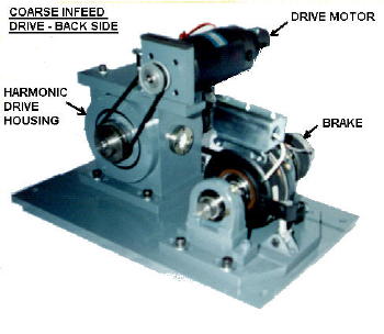 feed the wheel in at a constant rate during rough grinding. In additi
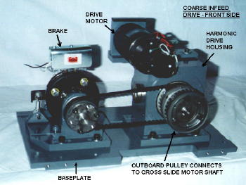 on, the wheel power is monitored to provide some load sensing feedback in
conjunction with the infeed controls. No position feedback is included
with the coarse infeed axis;
this
is not necessary, since the FFG/SLA includes a very precise position control.
The photos on the left show the coarse infeed mechanical drive subassembly.
on, the wheel power is monitored to provide some load sensing feedback in
conjunction with the infeed controls. No position feedback is included
with the coarse infeed axis;
this
is not necessary, since the FFG/SLA includes a very precise position control.
The photos on the left show the coarse infeed mechanical drive subassembly.
There are two electrical panels - an infeed drive station, and an operator station. The infeed drive station contains the Electrocraft Max 430 drive, transformer relays, and other miscellaneous devices and hardware. It can be mounted on the back of the carriage, since it does not have to be accessible to the operator during normal operation. The operator station must be mounted in a convenient area on the carriage platform, since it contains the pushbuttons, selector switches, and meters that have to be accessed during grinding. With this option, there is an automatic infeed screen supplied with the FFG program, in addition to the aforementioned displays. This AI screen provides a convenient operator interface for enabling both the coarse and precision continuous and end infeed motions, as well as load sensing functions. All the rate and infeed settings are done through this screen (satellite work station is a requirement). A load sensor is also included that measures the motor horsepower, and feeds this signal back to the operator station. The operator uses the "span" and "read set point" adjustments to set the load thresholds. There are other functions that can be included as well, like "short stroking" and automatic wheel approach. Coarse infeed has more appeal for hot mill applications than for cold mills, and/or for customers who want one operator to run more than one grinder.