INSTALLATION EXAMPLES: CINCINNATI TT ROLL GRINDER
COMPUTERIZED CROWNER RETROFIT SYSTEM
The photo immediately below shows the
crown drive assembly on a typical Cincinnati traveling table roll grinder.
This is the standard mechanical crowning arrangement which was being used before
the conversion to the RGB comp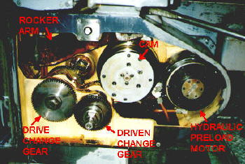 uterized
crowner installation. The drive change gear shaft is connected through a
spur gear interface to the table rack and pinion assembly. The cam
rotation is controlled by the selection of the change gears, which drive a 2:1
spur gear reduction to actuate the cam shaft. This particular Cincinnati
design utilized a hydraulic motor to apply a constant preload torque to
eliminate backlash in the drive train. The cam eccentricity is set for the
desired crown. Rotation of the cam lifts the crown lever rocker arm, which
in turn applies a magnified lifting force to the back of the camber base that
tilts about a V-block pivot axis at the front.
uterized
crowner installation. The drive change gear shaft is connected through a
spur gear interface to the table rack and pinion assembly. The cam
rotation is controlled by the selection of the change gears, which drive a 2:1
spur gear reduction to actuate the cam shaft. This particular Cincinnati
design utilized a hydraulic motor to apply a constant preload torque to
eliminate backlash in the drive train. The cam eccentricity is set for the
desired crown. Rotation of the cam lifts the crown lever rocker arm, which
in turn applies a magnified lifting force to the back of the camber base that
tilts about a V-block pivot axis at the front.
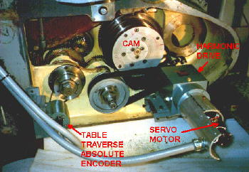
The photos below show the same machine
after the crowner retrofit. The change gears have been remo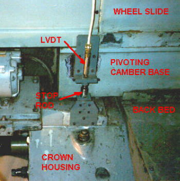 ved,
and an absolute encoder is connected through a timing belt interface to the
"drive" change gear shaft. The DC servo motor operates through a harmonic
drive reducer and timing belt to turn the "driven" change gear shaft, which
rotates the cam in the conventional manner. Cam eccentricity is set to a
specified value based on the customer's maximum crown and infeed requirements.
The hydraulic preload motor has been removed, since it is not needed for this
design (due to the fact that the gravity loading is always on
ved,
and an absolute encoder is connected through a timing belt interface to the
"drive" change gear shaft. The DC servo motor operates through a harmonic
drive reducer and timing belt to turn the "driven" change gear shaft, which
rotates the cam in the conventional manner. Cam eccentricity is set to a
specified value based on the customer's maximum crown and infeed requirements.
The hydraulic preload motor has been removed, since it is not needed for this
design (due to the fact that the gravity loading is always on
 one
side of the cam, resulting in a constant preload torque on the gear train).
The LVDT is mounted to measure the tilting motion of the camber base, and
provides the linear feedback signal to close the servo loop.
one
side of the cam, resulting in a constant preload torque on the gear train).
The LVDT is mounted to measure the tilting motion of the camber base, and
provides the linear feedback signal to close the servo loop.
Traveling table grinders are ideally suited for RGB crowner retrofit installations since the SCA control panels and associated wiring are mounted on the non-traversing elements of the machine, eliminating the need for electrical service carriers. Also, the FFG cabinet can be mounted adjacent to the operator station on the floor, eliminating the need for a satellite work station. Actual startup down time can be as little as one day, since most of the installation work can be done with the grinder still in the production mode. As can be seen from the photos, it would be an easy matter to revert back to the manual crowning system should it ever be required in an emergency situation.