INSTALLATION EXAMPLES: CINCINNATI TRAVELING CARRIAGE ROLL GRINDER
COMPUTERIZED CROWNER RETROFIT SYSTEM
The
existing Cincinnati is a model OM filmatic spindle design traveling carriage
grinder typical of many in the field. It includes a mechanical cam type
crowning device for grinding sinusoidal shapes on the
roll bodies. See the attached schematic on the right which depicts the
manual crowne r
design, along with a photo which shows the change gear portion of this
mechanical crowner assembly. The carriage motor drives through a set of
spur gears to the main carriage worm drive shaft. The output side of the
worm gear operates through another spur gear reduction to the carriage rack and
pinion assembly. A set of bevel gears on the main
r
design, along with a photo which shows the change gear portion of this
mechanical crowner assembly. The carriage motor drives through a set of
spur gears to the main carriage worm drive shaft. The output side of the
worm gear operates through another spur gear reduction to the carriage rack and
pinion assembly. A set of bevel gears on the main
 worm shaft transfers
power to a cross shaft which connects to the input or "drive" change gear shaft.
The output change gear or "driven" shaft is common with the first crown drive
worm reduction. The output side of the worm gear is coupled to the cam
worm assembly through a long connecting shaft running parallel to the bed ways.
This last worm reduction is built into the cam housing and is integral with the
rotating cam assembly. Therefore, as the carriage traverses along the bed,
the cam rotates.
worm shaft transfers
power to a cross shaft which connects to the input or "drive" change gear shaft.
The output change gear or "driven" shaft is common with the first crown drive
worm reduction. The output side of the worm gear is coupled to the cam
worm assembly through a long connecting shaft running parallel to the bed ways.
This last worm reduction is built into the cam housing and is integral with the
rotating cam assembly. Therefore, as the carriage traverses along the bed,
the cam rotates.
The "cam" is really not a cam in the true sense, but rather a double eccentric which is offset a specific amount from the true center of rotation. A cam follower, set in a slide member, rides the eccentric, and is made to translate vertically as the cam rotates.
This crowning motion is imparted to the grinding wheel through the tilting wheelhead cambering system, which consists of a simple trunnion pivot arrangement, with support points at the two front pivots and the center mounted cam follower bearing at the rear. Mechanical superposition of the crown input with the normal handwheel slide infeed is achieved with this system. The normal wheel infeed occurs between the camber base and the upper slide member.
It is important to recognize that the crown shapes that can be produced from this kind of bellcrank eccentric are sinusoidal in nature, since the principles of simple harmonic motion apply. Over the years, it has been found that a 70 degree portion of a cosine curve (the cam rotates +/- 70 degrees from the TDC position) most closely approximates the desired theoretical catenary or parabolic crown shapes required to compensate for roll deflections in the mill. It is a simple matter to vary this shape to other cosine angles (i.e.: 90 degrees, 120 degrees, etc.) by using different combinations of change gears. A chart is provided to select the appropriate change gears for a particular roll face and angle of cam rotation. But no matter what combinations of gears are used, the crown will always be a portion of a cosine curve. The amount of crown is controlled by fixing the total offset of the cam through the vernier adjustment built into the cam mechanism. The crown charts tabulate these offsets or eccentricity as a function of the required crown.
This mechanical system as described has the advantage of simplistic operation, but is limited to the development of pure sinusoidal crown shapes only. The SCA crowner retrofit addresses this issue, by retaining the basic elements of the proven cam type system for actuating the camber tilt infeed, and combining it with a state of the art computer system (FFG) and customized software (FFP) for producing any desired roll shape.
The SCA
accomplishes these objectives by using the existing eccentric cam with a fixed
preset offset to actuate the wheelhead camber tilt system in the conventional
manner. The existing drive train is essentially decoupled at the change
gear interface. On what was the "driven" change gear shaft, a DC servo
motor operates through a double timing belt reduction into the conventional gear
train to produce cam rotation. Carriage position is monitored using a
multi-turn absolute encoder connected through appropriate belting to a rack and
pinion drive on the side of the back bed. This feeds the computer to
produce digital display outputs of carriage position as well as producing the
signals for the "x" axis of the crown profile. The cam is offset a
specific amount (determined at startup for opti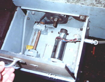 mized
perform
mized
perform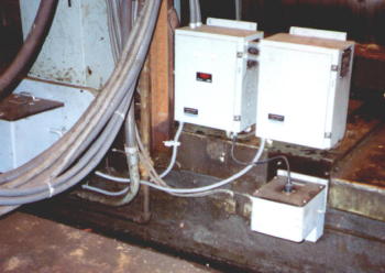 ance).
There
are no further adjustments required to the cam. With t
ance).
There
are no further adjustments required to the cam. With t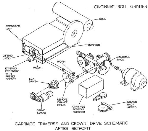 his fixed
eccentricity, the wheel infeed can be controlled very accurately with the servo
motor. The schematic on the left depicts the revamped crowner setup, and
the photos on the right show the same Cincinnati grinder with these SCA crowner
components installed.
his fixed
eccentricity, the wheel infeed can be controlled very accurately with the servo
motor. The schematic on the left depicts the revamped crowner setup, and
the photos on the right show the same Cincinnati grinder with these SCA crowner
components installed.
The command signals are produced by the computer located in the FFG enclosure on the floor. An IBM compatible industrial PC interfaces through a D/A board and other peripheral devices to provide the outputs to the SCA. The computer receives digital inputs from the absolute encoder, and produces profiles from the resident software. The outputs go through the D/A board, then into summing circuits to command the servo motor for "y" axis positioning.
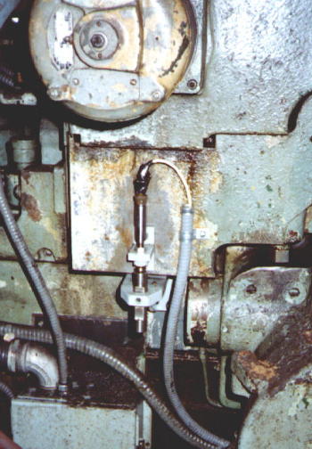
Since the crown actuator is a non-linear device, a LVDT is mounted on the back of the wheelhead to measure the crowning action directly, taking into account the magnification effect due to the pivot ratio. This then forms the linear feedback to complete the positioning servo loop. The LVDT mounting is shown in the adjacent photo.