INSTALLATION EXAMPLES: CHURCHILL ROLL GRINDER
COMPUTERIZED CROWNER RETROFIT SYSTEM
The two
photos immediately below show a 72" x 180" Churchill roll grinder as installed
in a paper mill in Australia befo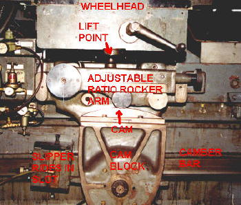 re the RGB crowner retrofit. The design
of the crowning mechanism on this vintage Churchill grinder utilizes a long
camber bar mounted on the side of the back bed, pivoted at the center, and
extending the full length of the wheel travel. This bar is tilted at an
arbitrary angle of inclination, and clamped
at each end. A slipper rides in a slot machined in the camber bar, and the
angular movement of the slipper is transferred to the cam block as the carriage
traverses along the bed. A camber bracket bolted to the back of the
re the RGB crowner retrofit. The design
of the crowning mechanism on this vintage Churchill grinder utilizes a long
camber bar mounted on the side of the back bed, pivoted at the center, and
extending the full length of the wheel travel. This bar is tilted at an
arbitrary angle of inclination, and clamped
at each end. A slipper rides in a slot machined in the camber bar, and the
angular movement of the slipper is transferred to the cam block as the carriage
traverses along the bed. A camber bracket bolted to the back of the
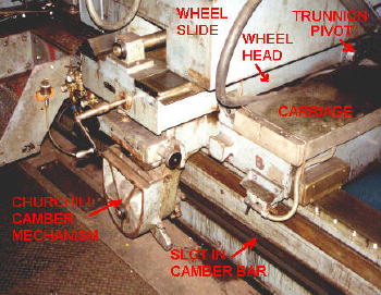 carriage supports the camber mechanism. A cam (convex or concave) is
bolted to the cam block. This cam is made to rotate through a fixed angle
either side of center as the carriage traverses the roll face. The
movement of the cam imparts lift to the roller arm, the purpose of which is to
vary the pivot ratio for setting the crown magnitude. The roller arm
reacts with the wheelhead via a steel ball pivot support. This crowning
motion is imparted to the grinding wheel through the tilting action of the
wheelhead, which pivots about a trunnion bearing approximately under the wheel
centerline. The crowning motion, then, is superimposed with the normal
wheel slide infeed as controlled by the operator. Although this camber
design has served the industry well over the years, it does have a number of
restrictions and limitations, which led this customer to the purchase the RGB
Engineering FFG/FFP/SLA computerized crowner retrofit.
carriage supports the camber mechanism. A cam (convex or concave) is
bolted to the cam block. This cam is made to rotate through a fixed angle
either side of center as the carriage traverses the roll face. The
movement of the cam imparts lift to the roller arm, the purpose of which is to
vary the pivot ratio for setting the crown magnitude. The roller arm
reacts with the wheelhead via a steel ball pivot support. This crowning
motion is imparted to the grinding wheel through the tilting action of the
wheelhead, which pivots about a trunnion bearing approximately under the wheel
centerline. The crowning motion, then, is superimposed with the normal
wheel slide infeed as controlled by the operator. Although this camber
design has served the industry well over the years, it does have a number of
restrictions and limitations, which led this customer to the purchase the RGB
Engineering FFG/FFP/SLA computerized crowner retrofit.
The two
photos below show the same machine with the new Servo Linear Actuator (SLA)
installed. This consists of a s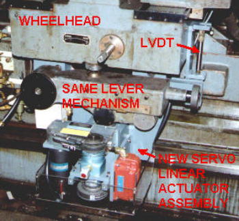 pecial ball screw driven by a DC servo
motor through a harmonic drive reducer and timing belt
arrangement.
Note that the ball screw operates the same roller lever mechanism, which lifts
the wheelhead in the conventional manner. Due to the gravity preload
effect, backlash is minimized on all the drive train elements on the output side
of the harmonic drive reducer. Since the harmonic drive is essentially
backlash free, as are the timing belt drives, the whole SLA mecha
pecial ball screw driven by a DC servo
motor through a harmonic drive reducer and timing belt
arrangement.
Note that the ball screw operates the same roller lever mechanism, which lifts
the wheelhead in the conventional manner. Due to the gravity preload
effect, backlash is minimized on all the drive train elements on the output side
of the harmonic drive reducer. Since the harmonic drive is essentially
backlash free, as are the timing belt drives, the whole SLA mecha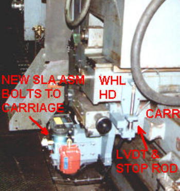 nism provides a
quick response servo drive with a very fine resolution for accurate positioning
of the wheel axis. A LVDT is mounted in such a way as to measure the
tilting motion of the wheelhead, and provides the position feedback to complete
the servo loop.
nism provides a
quick response servo drive with a very fine resolution for accurate positioning
of the wheel axis. A LVDT is mounted in such a way as to measure the
tilting motion of the wheelhead, and provides the position feedback to complete
the servo loop.
In
addition to the crowning functions, a precision infeed handwheel is included to
give the operator control of the wheel movement using the "tilt" axis instead of
the conventional infeed ways, which have considerable backlash, lost motion, and
stick-slip. The photo on the right shows the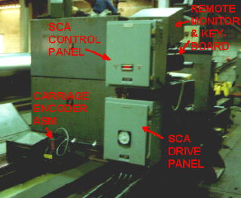 location of the
carriage position encoder, which is driven off the carriage drive rack.
The SCA control cabinet houses the crowner summing and LVDT conditioner boards,
power supply, and miscellaneous devices. The SCA drive cabinet contains
the servo drive and transformer. The satellite monitor and keyboard
mounted on the carriage allow the operator to control crowning functions from
this location, as well as from the FFG station.
location of the
carriage position encoder, which is driven off the carriage drive rack.
The SCA control cabinet houses the crowner summing and LVDT conditioner boards,
power supply, and miscellaneous devices. The SCA drive cabinet contains
the servo drive and transformer. The satellite monitor and keyboard
mounted on the carriage allow the operator to control crowning functions from
this location, as well as from the FFG station.